
How do you use polar coordinates in Blender?
Anyone who starts learning about CAD drawing eventually will get in touch with the coordinate system of those softwares. They are a powerful and reliable way to control lengths and distances. You can specify a point in space using values for X and Y for a 2D design and eventually include a Z location.
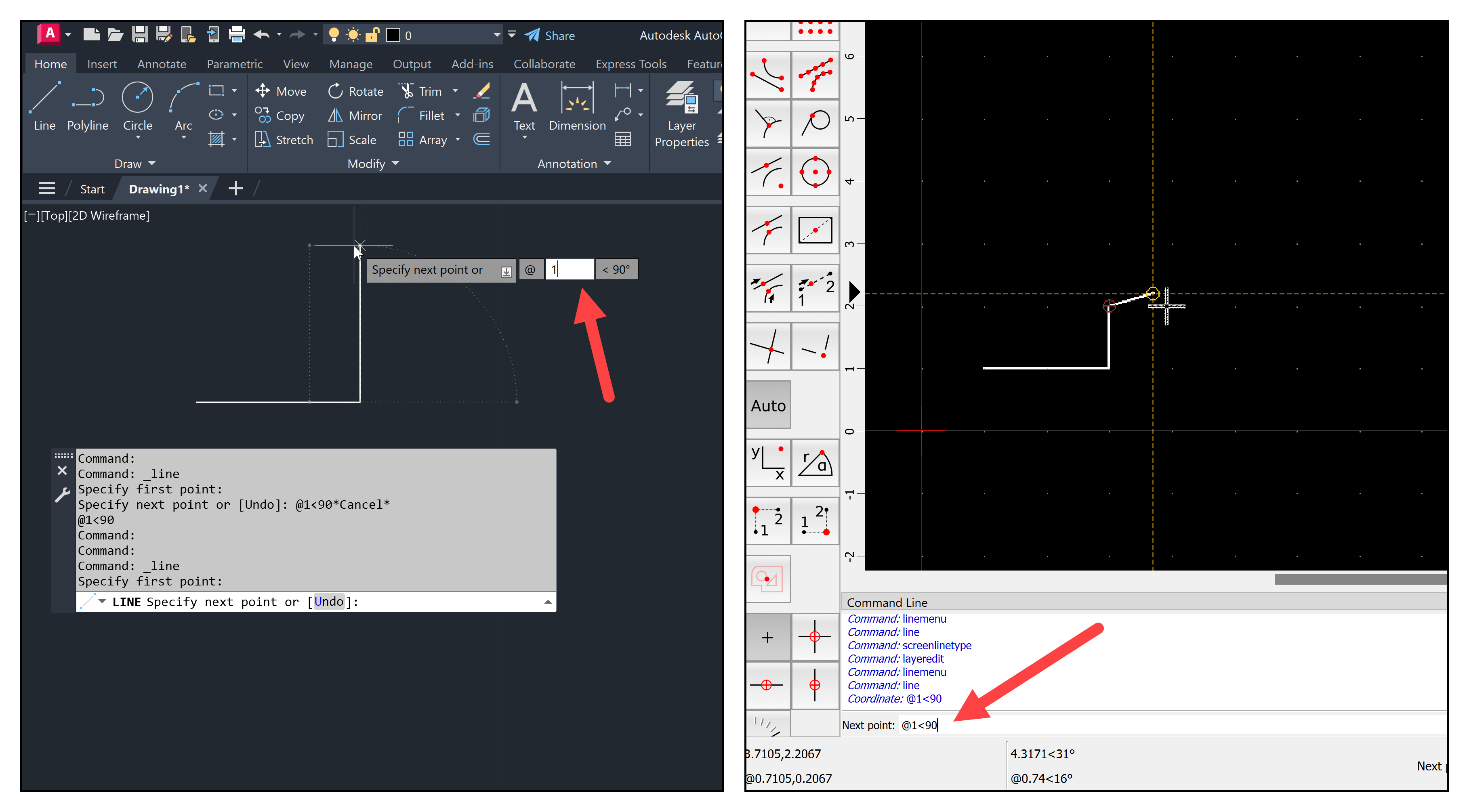
One of those systems has the name of Polar Coordinates, and it uses a combination of distance and angle to locate points and draw entities. A common way to write those coordinates is with a notation like “@distance<angle,” which translates into @1<90 for one unit with a direction of ninety degrees.
In the example below, we have the same system used in AutoCAD and QCAD.
Do you know that we can use polar coordinates in Blender? The notation used to create the lines is different but is the same principle. We must enable an Add-on called PDT (Precision Drawing Tools) to use this system.
To enable PDT, open the Edit → Preferences menu and search for PDT in the Add-ons tab. Once you enable the Add-on, a new tab appears in the 3D Viewport Sidebar. From the PDT tools, we have a section named PDT Command Line that works in a similar way to a CAD tool.
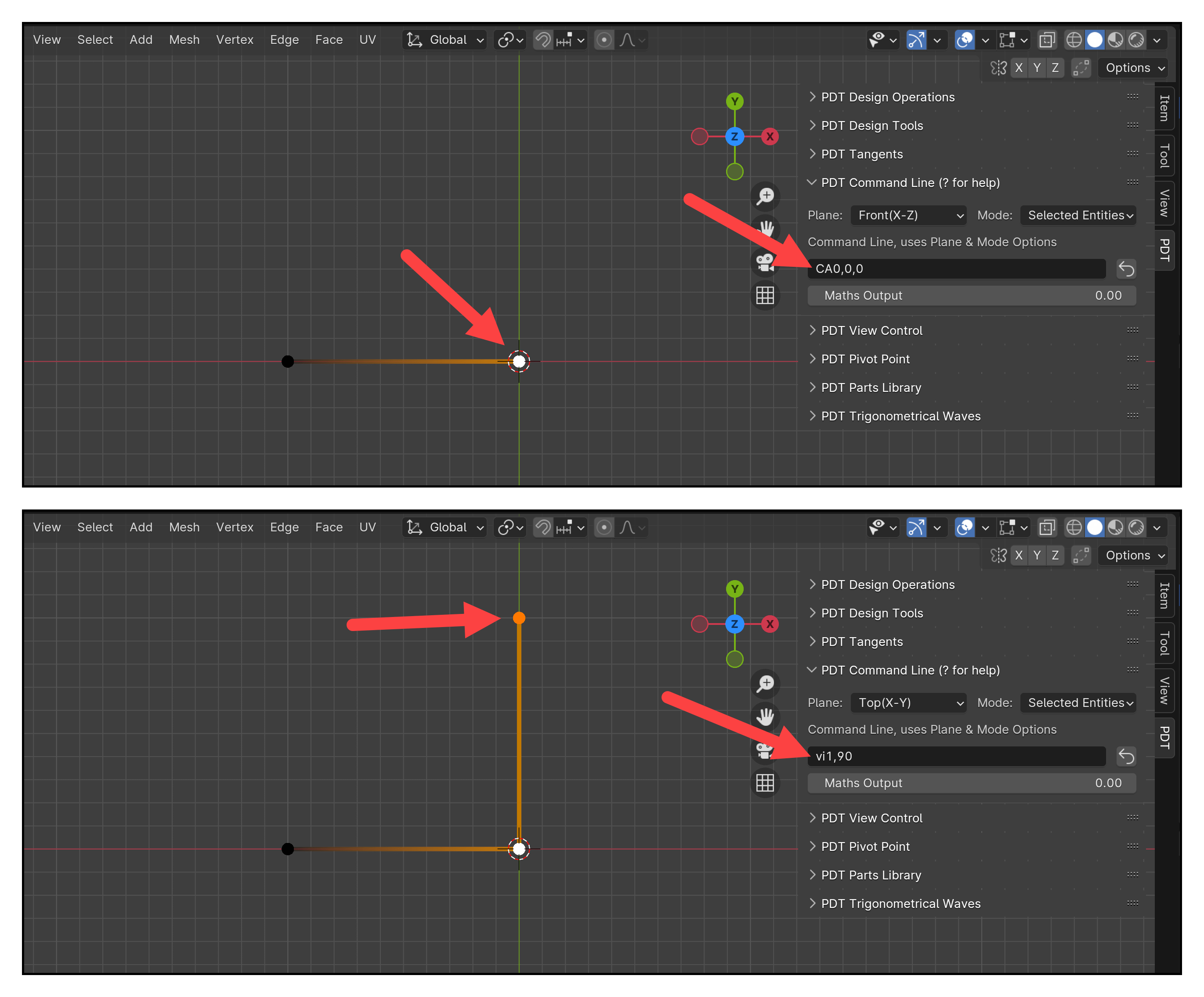
You can write commands and coordinates there to make extrusions or move your 3D Cursor. For instance, we can use the following commands:
- v: To extrude a vertex
- i: To use an inclination or angle, which works like Polar Coordinates
Next to those two letters, you can write a distance and angle separated by a comma. The command will look like this: vi1,90. If you select a vertex in Edit Mode, use this command with PDT, and press ENTER, you get a line with one unit with a ninety-degree angle.
There is a noticeable difference in how you write the coordinates from a CAD tool and Blender, but the principle is the same. Since we use a 3D environment in Blender, you must set your Plane in PD before typing any polar coordinates. The example above shows that I'm using the Top(X-Y) option.
Learning to use Blender and CAD
If you want to learn about Blender modeling tools for architecture and CAD, we have a lot of useful resources here in Blender 3D Architect. From complete guides to workshops:
- Blender for architecture (Workshop)
- Blender 4.0: Precise Modeling for Architecture (Paperback) – (eBook)
- Blender for technical drawing (Workshop)
- QCAD for technical drawing (Open-source version of QCAD)
We have the Blender 4.0: Precise Modeling for Architecture covering PDT applied to architectural design from these resources.